
Page 97 - Hydraulics Cylinder
P. 97
10.2
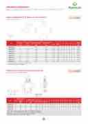
I DI FLUSSO A 2 VIE IN ACCIAIO
3 6 6 10 10 20 20 32 25 40
250 300 250 300 250 300 250 300 250 300
PORTATA MIN* CODICE SIGLA MIN FLOW
CODE TYPE Lt. / min
PORTATA MAX*
MAX FLOW Lt. / min
PRESS. ESERCIZIO
WORKING PRESSURE Bar
PICCO DI PRESSIONE
PEAK PRESSURE Bar
V1020 DFL 1 - 3 1 3 250 300
UK Hydraulic components • DE Hidraulik Komponenten • FR Composants hydrauliques • ES Componentes hidráulicos
V1021 DFL 3 - 6
V1022 DFL 6 - 10
V1023 DFL 10 - 20
SCHEDA TECNICA/ TECHNICAL DATASHEET
V1024 DFL 20 - 32
V1025 DFL 25 - 40
V1026 DFL 40 - 60 40 60 250 300
V1027 DFL 60 - 80 60 80 250 300 Valvole equilibratrici di flusso a 2 vie in acciaio
TIPO • TYPE DFL
L ER
2 ways steel flow divider *I valori di portata si riferiscono all’ingresso P *Capacity values refers to input P
TIPO / TYPE DFL
SCHEMA IDRAULICO
HYDRAULIC DIAGRAM
AYS STEEL
W DIVIDER
Art.
Portata min*
Min flow
Lt./min
CODICE
CODE
V1020
V1021
V1022
SIGLA P
Portata max*
TYPE GAS
Min flow
DFL 1 - 3 G 3/8”
Lt./min
DFL 3 - 6 G 3/8”
DFL 6 - 10 G 3/8”
A - B L L1 L2
Press. esercizio
GAS mm mm mm
Working pressure G 3/8” 117 Bar53 40 G 3/8” 117 53 40
G 3/8” 117 53 40
PESO H H1 S WEIG mm mm mm Kg.
Picco di pressione
Peak pressure
2,000
70 45 40
Bar
70 45 40 2,000
70 45 40 2,000
HT
P GAS
A-B GAS
L
L1
L2
H
H1
S
Peso Weight Kg
ND OPERATION:
MQ267009
alves allows the division of inlet fl
50/50) and they unify it in the rev
ow into two equVa10ls23 1
erse direction irVr1e0-24
3
DFL 10 - 20 G 3/8”
DFL 20 - 32 G 3/8”
G 3/8” 117 25053 40 G 3/8” 117 53 40
300
70 45 40 2,000
70 45 40 2,000
G 3/8”
G 3/8”
117
53
40
70
45
40
2,000
e of any pressure differences and d when MtwoQe2qu6al7a0ctu1a0tors, that
flow. These valves
are not mec3hani-
V1025
6
DFL 25 - 40 G 1/2”
G 3/8” 117 25053 40
300
70 45 40 2,000
G 3/8”
G 3/8”
117
53
40
70
45
40
2,000
oupled, supplied by the same pum
MQ267011
ngle distributor, must move simulta
nd output.
p and controlleVd1026 neously both at
SCHEDA TECN
6
ICA/VT1EC0H2N7ICAL
DFL 40 - 60 G 1/2” DFL 60 - 80 G 1/2”
DATASHEET
10
G 3/8” 117 53 40 G 3/8” 117 25053 40
70 45 40 2,000 70 43500 40 2,000
G 3/8”
G 3/8”
117
53
40
70
45
40
2,000
MQ267012
10
20
250
300
G 3/8” 2
G 3/8”
20
117
53
40
70
45
40
2,000
IALS AND FEATURES: zinc-plateMd sQte2el67013
20
32
250
300
G 3/8”
G 3/8”
117
53
40
70
45
40
2,000
l parts: hardened and ground stee
MQ267014
BUNA N standard and Teflon
ss: by diameter combination. Min
l
r leakage25
40
250
300
G 1/2”
G 3/8”
117
53
40
70
45
40
2,000
r stroke error tolerance of ± 3% ation difMfereQnc2e6s a7re0c1om5pendate
ny syn-
d by the 40
60
250
300
G 1/2”
G 3/181”
117
53
40
70
45
40
2,000
l position of the stroke.
ATIONS:
MQ267017
60
80
250
300
G 1/2”
G 3/8”
117
53
40
70
45
40
2,000
ct P to pressure flow and A and B to the actuators.
* I valori di portata si riferiscono all’ingresso P * Capacity values refers to input P
2W FLO
USE A
These v parts ( spectiv are use cally c by a si input a
MATER
Body:
Interna
Seals: Tightneo Cylinde A chronis
termina
APPLIC Conne
11.1
V0512 VABP 3/8” 20 40 60
TIPO • TYPE VABP
SCHEDA TECNICA/ TECHNICAL DATASHEET
VABP
V0514 VABP 3/4” Two pump “hi-low” unloading valves
CODICE
CODE
SIGLA
TYPE AP
PORTATA MAX
MAX FLOW Lt. / min
BP T
PRESSIONE MAX PESO
MAX PRESSURE WEIGHT Bar Kg
300 1,748 350 2,342 350 3,970
Valvole di esclusione alta-bassa pressione
V05
13
1/2
”
30
40 80
50
80
120
NE ALTA-BASSA PRESSIONE
TIPO / TYPE VABP
SCHEMA IDRAULICO
HYDRAULIC DIAGRAM
sede tappata per l’eventuale applicazione di un manometro
capped port for eventual manomether montage
MOLLE STANDARD - STANDARD SPRINGS
VALVOLA
VALVE
VABP 3/8”
BP
(BAR)
20-80
AP
(BAR)
50-350
WO PUMP “
Art.
NLOADING
I-L
A
A
CO
L
P
DICE
COD
V0512
E
Portata max
W”
Max flow
ES
Lt./min
BP
GAS
G 3/8
SIGLA AP
TYPE GAS
BP
VABP 3/8” G 1/4”
TU GAS
” G 3/8
Press. max MaT xpL resL1surL2e
Bar
GAS mm mm mm
” G 1⁄2” 100 142 155
AP
GAS
L3 L
mm m
50 3
BP
GAS
4 L5
m mm
0 20
U
GAS
L6 L7
mm mm
13 69
VABP 1/2 VABP 3/4
T
GAS
65
H1
mm
” ”
HL2 mm
8,5
20-80 20-80
H3L1 mm
6,5
50-3 50-3
HL 2 S mm m
80 3
50 30
L3
m
0
L4
L5
L6
L7
H1
H2
H3
H
S
Peso Weight Kg
E AND OPERATION:
svalvMeisQu2se6d7in0a20parall er to release the excess of t
V0513
el-2wo0rki hVe05h1ig4h
ngpumps4cir0cuitin
er VflAoBwP 3p/u4”mpGto1/t2h”e G 3/4
VABP 1/2” G 3/8” G 1/2
60
” G 1/2
” G 3/4
300
” G 3/4” 105 147 160
” G 1” 140 187 212
G1/4”
54 3
52,5 42,
G3/8”
6 18
5 20
G3/8”
15 73
20 95
G1/2”
65
65
100
27
17
142
8
8
155
90 3
100 4
5 50 0
30
20
13
69
65
8,5
6,5
80
30
1,748
k when this gets the require
MQ267021
moment and on the actuat
d press
30
or work
ure setting. Since
s with the lower flow
50
80
350
G3/8”
G1/2”
G1/2”
G3/4”
105
147
160
54
36
18
15
73
65
17
8
90
35
2,342
ps at higher pressure, cons
MQ267022
uming l
40
ess energy.
80
120
350
G1/2”
G1/4”
G1/4”
G1”
140
187
212
52,5
42,5
20
20
95
65
27
8
100
40
3,970
Molla “BP” • “BP” spring • Feder “BP”: B = 20:80 bar (Standard)
TERIALS AND FEATURES:
dy: zinc-plated steel
rnaMl comlploane“nAts:Pgr”ou•nde“dAanPd”hasrdperneidnsgtee•l Feder “AP”: D = 50:350 bar (Standard)
ls: BUNA N standard
Montaggio in linea • Line mounting • Reihenmontage 224 htness: minor leakage
Materiale • Material: Acciaio • Steel • Stahl
o, di
ato uato- ne
e e
alla zo e
THO UVV
US
Thi ord tan this pum
MA Bo Inte Sea Tig
APPLICATIONS:
Connect BP to the higher flow pump, AP to the lower flow pump, T to the tank, M to the eventual manometer and U as for necessity.
Temperatura olio: 50°C - Viscosità olio: 30 cSt
Oil temperature: 50° C - Oil viscosity: 30 cSt
97
E
C
a n
o
