
Page 96 - Hydraulics Cylinder
P. 96
UK Hydraulic components • DE Hidraulik Komponenten • FR Composants hydrauliques • ES Componentes hidráulicos
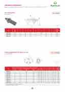
Vite strozzatrice
Throttle screw
TIPO • TYPE VS
9.12
SCHEDA TECNICA/ TECHNICAL DATASH
VITE STROZZATRICE
SCHEMA
HYDRAULI
Art.
G GAS
L
L1
L2
H
D
E
E1 TH SC
OTTLE
Peso
Weight EW Kg
MQ261050
G 1/4”
SCHEDA TECNICA
36 CODICE CODE
/ TECHNICAL DATASHEET
SIGLA
TYP
53
E
G L L1
GAS 1mm5 mm
L2 H D
mm mm7 mm
E E1 PESO 2,5 WEIGHT
kg
mm mm
13
19
0,046
MQ261052
G 3/8”
39 R1351
58
VITE STROZZATRICE 1/4”
15
G1/4” 36 53
15 7 8 2,5IMPIE Vite u
G13O: 19 3 0,046 tilizzata sugli attuatori
come strozzatore
13
22 USE A This scr
0,074
D OPERATION:
ew is used on actuators as
MQ261053
G 1/2”
R1361 46 R1371
VITE STROZZATRICE 3/8” VITE STROZ6ZA2TRICE 1/2”
G3/8” 39 58 G1/2” 146 62
15 8 3
16 8 8 4bidire
regol
13 22 0,074
13 27
zionale nei casi in cui s
4
0,136
azione “grossolana” o
i necessiti di una
13
quando le dimensioni
restrict 27 or whe
r when adjustment can be n small d0im,e1ns3io6ns don’t a
R R
10
10.1
Valvole equilibratrici di flusso a 2 vie
250 300
2 ways flow divider
CODICE SIGLA
CODE TYPE
PORTATA MAX*
MAX FLOW Lt. / min
1 36
10 20 32 40 60 80
tuatore.
V1001 V - EQ 8 V1000 V - EQ 10
V1002 V - EQ 15 6
V1003 V - EQ 20 10
V1004 V - EQ 22 20
V1005 V - EQ 25 25
V1006 V - EQ 30 40
V1007 V - EQ 50 60
3
250
250
250
250
250
250
250
*I valori di portata si riferiscono all’ingresso P
*Capacity values refers to input P
PORTATA MIN*
MIN FLOW Lt. / min
AvPRvEiStSa. rESeERlCaIZIvOite diretPtICaCmOeDnI PtReESsSuIOlNleE bocche dell’at-
PEAK PRESSURE Bar
300 300 300 300 300 300 300
di ingombro non consentono il montaggio di uno strozzatore in linea. Caratterizzato dal prezzo economico, non offre tuttavia la sicurezza di una valvola di regolazione flusso.
bi-directional
o a little imprecise llow mounting of
an in-line restrictor. It’s a very cheap solution, but it doesn’t guarantee the same security of a restrictor valves.
MATERIALS AND FEATURES: Body: zinc-plated steel
APPLICATIONS:
Screw in the screw directly on actuator’s ports
SCHEDA TECNICA/ TECHNICAL DATASH
T
SCHEMA I
HYDRAULIC
A DIVIDER
MATERIALI E CARATTERISTICHE:
Corpo: acciaio zincato
MONTAGGIO:
214
WORKING PRESSURE
Bar
N
9
VALVOLE EQUILIBRATRICI
DI FLUSSO A 2 VIE
TIPO • TYPE V-EQ
Art.
Portata min* Min flow Lt./min
Portata max*
Min flow
Lt./min
CODICE
CODE
Press. esercizio
Working pressure
SIGLA P A - B L
Bar
TYPE GAS GAS m
Picco di pressione
Peak pressure
L1 L2 L3
Bar
m mm mm mm
P
GAS
ØG H
m
m
m
A-B
GAS
m
H1
mm
LS mm
L1
PES
WEIG Kg.
OL2 HT
L3
ØG
H2
W
H1
YS
S
Peso
FLOW
Weight Kg
MQ261537
1
V1001
3
V1000
V - EQ 8 G 3/8” G 3/8” 11
250
V - EQ 10 G 3/8” G 3/8” 11
7 53 40 45 I
300
7 53 40 45 i
MP7IEGO: 3
G 3/8”
alvole che c
73
ngresso in d
5 68
G 3/8”
onsentono l
5 68
ue parti ugu
117
a divisio
ali (50/
48
48
53
ne del
50), me
1,2
1,2
7040 70
ntre nel
fluido in
45
la
7
35
US
Th
eq
E AND
68
ese valv
uals pa
OPERA
48
es allo
rts (50/
TION:
1,270
ws the division of
50) and they uni
MQ261538
3
V1002
6
V1003
V - EQ 15 G 3/8” G 3/8” 11
250
V - EQ 20 G 3/8” G 3/8” 11
7 53 40 45 d
300 d 7 53 40 45
ire7zione op3 aGll7a3va/r8ia”z3i
p5ostalo6r8iuni
o5nGed3i/p8
”ssi 6re8
fican4o8 i
o1ne1g4 8e
7
ndipe1n,2 ne5ra3ta1,d2
d8e0ntem 8a0g4li0att
ente ua4-5
7
dir 35Th
ection i es6e 8valv
ndipen es4a8re
ently of any pre used1w,2he7n0twoe
MQ261540
6
V1004
10
V1005
V - EQ 22 G 3/8” G 3/8” 11
250
V - EQ 25 G 1/2” G 3/8” 11
7 53 40 45
t
300
d 7 53 40 45 t
ori e dalla lo
73
G 3/8”
ue attuatori
e, a7limentat3i
ro portata.
5 68
G 3/8”
uguali, non
5dalla st6e8ssa
Vengon
117
accopp
pom4p8a
48
o utilizz
53
iati mec
e reg1o,2l
1,2
ate qua
8040 8a0ti dall
canica
o
ndo
45
en-
7
35
no
an
ne
t mecha
68
d contr
ously b
nically
48
olled by
oth at in
coupled, supplie
1,280
a single distribu
put and output.
MQ261542
10
V1006
20
V1007
250
V - EQ 30 G 1/2” G 3/8” 11
V - EQ 30 G 1/2” G 3/8” 11
300 a 7 53 40 45
7 53 40 45
s
tesso distrib
mGen3te/i8n”ent 73
73
utore, devon
rGata3e/in8u”sc 5 68
5 68
o muov
i1ta1.7 48
48
ersi con
531,2 1,2
tempor
60
60
40
ane-
45
7
35
68
48
1,280
MQ261543
20
32
250
300
ATERIALI E
G 3/8”
orpo: ghisa
omponenti i
CARATTERI
G 3/8”
nterni: accia
STICHE
117
io temp
: 53 rato ter
40
micame
45
nte e
7
35
M Bo
Int
ATERIA dy: cast
68
ernal p
LS AND iron
48
arts: ha
FEATURES:
1,280
rdened and grou
MQ261544
25
40
250
300
r
ettificato Guar1niz/i2on”i:
BGUN3A/N8”sta
n1d1ar7d
e T5efl3on
40
218
45
7
Se 35Tig
als: BU h6tne8ss:
NA N st by4d8ia
andard and Tefl ete1r c,o2m8b0inatio
MQ261546
40
60
250
300
T T c
enuta: per a
G 1/2”
olleranza: <
ompensate
ccoppiamen
G 3/8”
2% sulla co
a fine corsa
to. Trafi
117
rsa. Ev
del cilin
lament
53
entuali d
dro.
trascur
40
ifferen
abile
45
ze sono
7
35
Cy
ch
ter
linder s
68
ronisati
minal p
troke er
48
on diffe
osition
ror tolerance of
1,260
rences are comp
of the stroke.
MQ261547
60
80
250
300
GON1TA/2GG”I ollegare P
OG: 3/8” all’alimentazi
117
one e
53
e Ba
40
li attua
45
tori.
7
35AP Co
PL6IC8AT nnect P
IO4N8S: to pres
1,260
sure flow and A
* I valori di portata si riferiscono all’ingresso P * Capacity values refers to input P
V inlet flow into two
d
fy it in the reverse ssure changes and fl qual actuators, that d by the same pump tor, must move simul
nd steel
on
n. Minor leakage
m
M
C C
G
M
C
m
o 2%. Any syn-
endated by the
A g andBtotheactuato
96
T
C
E
