
Page 87 - Hydraulics Cylinder
P. 87
6.1
UK Hydraulic components • DE Hidraulik Komponenten • FR Composants hydrauliques • ES Componentes hidráulicos SCHEDA TECNICA/ TECHNICAL DATASHEET
CODICE
CODE
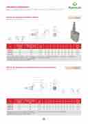
Valvole di sequenza ad azione diretta
Direct acting sequence valves
SIGLA
TYPE
VS2C 3/8” VS2C 1/2” VS2C 3/4”
PORTATA MAX
MAX FLOW Lt. / min
35 70 110
RANGE DI PRESSIONE
PRESSURE RANGE Bar
350 350 400
TIPO • TYPE VS2C
V0640 V0660 V0665
AZIONE DIRETTA
SCHEMA IDRAULICO
HYDRAULIC DIAGRAM
DIR
SEQ
USE A
Sequen sequen when a reachin ideal fo actuato
MATER
Body: Interna Seals: Poppet
APPLICATIONS:
TIPO / TYPE VS2C
SCHEMA DI MONTAGGIO
APPLICATION SCHEME
A
6
ECT ACTIN
Art.
UENCE V
G Portata max Max flow
LVELSt./min
Range di pressione Pressure range Bar
CO C-V CO GAS CO
L L1 L2
DICE/V • COD DICE/PP • CO
DICE/P
• COD L
L3
REGOLA
E/V
DE/PP Predisp
E/PP
L1
ZIONE - ADJ
osizione alla pi
L2
P
USTEMENT
Volantino • Ha ombatura • Ar
iomb
L
atu
ra • S 3
ndknob ranged for sea
ealin
4
L
g ca
p
Peso Weight Kg
G 3/8”
mm mm mm
74
mm
L4 L5
146
mm mm
L6
14
mm
HS
mm 7 mm
PESO/
WEIGHT
ling cap
L5
L6
H
S
ND OPERATION:
MQ261510
ce valve is used to feed
ce: it provides flow to th
MQ261512
primary circuit function
g the pressure setting. R rcirMcuiQts2w6ith1l5ow13press
2 cylinders in
eturn flow is free. It’s ure on the se1co1n0dary
35
CODICE SIGLA
C- V
CODE 350 TYPE GAS
V0640 VS2C 3/8” G 3/8”
V0665 400VS2C 3/4” G 3/4” MOLLE - SPRINGS (VS2C 3/
r as the pressures add to. Campo di taratura Incremento bar per riga Taratura standard Campo di taratura Incremento bar per riga Taratura standard Setting range (bar) Pressure increase (bar/turn) Standard setting Setting range (bar) Pressure increase (bar/turn) Standard setting
100 164 20
8” - 1/2”)
G 3/4”
Molla • Spring • Feder VS2C 3/8” - 1/2”: A = 10:50 bar - B = 20:100 bar - C = 10:180 bar (Standard) - D = 50:250 bar - E = 80:300 bar
IALS AND FEATURES: Q= 4l/min (bar) Q= 4l/min (bar)
zincM-ploatleldast•eeSl. pring • Feder VS2C 3/4” - 1/2”: C = 20:200 bar - D = 50:400 bar (Standard)
l paMrtso: nhatradgengeidoanind glrionuenad s•teeLl.ine mounting • Reihenmontage
BUNA N standard
10 - 180 standard 30 90
Materiale • Material: Acciaio • Steel • Stahl50 - 250 45 130 type: minor leakage 80 - 300 50 150
10 - 50* 7
30
20 - 200 40 160
20 - 100 12 75
50 - 400 standard 80 180
10
100
8016450 MOLLE -
33
50
20
SPRINGS (V
70 7 30 70 30
10010 40 S2C 3/4”)
55
51,172 5
1
Kg
,130
2,900
80
39
37
50
31
33
50
70
70
100
30
30
40
1,172
e secondary circuit
70
has been completed SCHED
V0660 350
A TECNICA/ TECHNICAL DATASHEET
VS2C 1/2” G 1/2”
74 146 14
G
1/
8
”
15
0
15
2
2
8
7
7
0
55 39
55
37
152
31
1
5
1,130
2,900
ATA
in)
Temperatura olio: 50°C - Viscosità olio: 30 cSt
Oil temperature: 50° C - Oil viscosity: 30 cSt
VS2C 3/4”
FLOW - Q (l/min)
VALVOLE DI SEQUENZA AD ANNULLAMENTO PRESSIONE PRIMARIA
For use with 2 actuators, follow the mounting instruc- tions indicated in the scheme. For different uses, mount the valve keeping into consideration that, when the valve reaches the setting pressure, the flow goes from V
6.2
SCHEDA TECNICA/ TECHNICAL DATASHEET
TIPO • TYPE VSQAPP
towards C, whilst flow is free from C to V.
Sequence valves
CODICE
CODE
V0642 V0662 V0667
SIGLA
TYPE
VSQAPP 3/8” VSQAPP 1/2” VSQAPP 3/4”
PORTATA MAX
MAX FLOW Lt. / min
35 70 110
RANGE DI PRESSIONE
PRESSURE RANGE Bar
350 350 400
ON REQUEST
• different setting range (see the table)
• other setting available (CODE/T000 please specify the desired setting)
*Per tarature inferiori a 70 Bar: Q = 12 l/min *For setting less than 70 Bar: Q = 12 l/min
162
Valvole di sequenza ad annullamento pressione primaria
6
VS2C 1/2”
FLOW - Q (l/min)
SCHEMA IDRAULICO
HYDRAULIC DIAGRAM
E
AN
e g
u
TIPO / TYPE VSQAPP
SCHEMA DI MONTAGGIO
APPLICATION SCHEME
CODICE/V • CODE/V
e
REGOLAZIONE - ADJUSTEMENT
Volantino • Handknob
M4
Art.
Portata max Max flow Lt./min
Range di pressione
Pressure rangIeMPIEG C- V L
E CODE TYP
B
ar
CODICE SIGLA Valvola
GAS mm
in sequ
COD O: C-V COD
GAS
L1 L2 L3
utilizzata princi
mm mm mm
enza due cilindri
ICE/PP • CO ICE/P • CO
L
palment
L4
mm
: al ragg
DE/PP Pre DE/PP
L1
L5 L6
per far
mm mm
iungime
disposizione a
L2
funzion
nto di un
H
mm
lla piombatur Piombatu
L3
areH1 mm
a • Arrange ra • Sealing
H2L4 S mm m
SE
d for sealing
cap
LUS5PESO/ WEIGH Seque
m Kg
it pro
QU
NLD6OP Tnce valv
vides flo
cap
NC
ERAHTIO e is use w to the
EV
:H1
d to feed seconda
ALV
H2
2 cylin ry circuit
ES
S
ders in s when a
Peso Weight
equence:
primary
Kg
MQ261515
35
V0642 VSQAPP 3/8” G 3/8” dete7r4mi
350
va ad a
V0662 VSQAPP 1/2” G 1/2” 80
na14to9 val5o5re di12ta
G 3/8”
limentare un sec
155 55 18
ratu2r0a, l
74
ondo att
19
a3v6alvol1
149
uatore.
36 1
a4 si apr3e9
55
La valvol
5 37
e 31
a 12 33
7020 3 70 3
0 circ1u,2i5t
36
settin
0 1,280
0 function
14
. Return
has be
39
flow is f
n compl
31
ree. Bei
eted rea
70
ng insen
ching th
30
sitive to
e pressure back 1,250
MQ261517
70
V0667 VSQAPP 3/4” G 3/4” 100 350 la direz
di riteg
no permette il lib
ioneGop1p/o2s”ta. E’
190 80 10
ero pass
in8se0nsib
25
aggio d
il1e5al5le
55 2
el flusso
con5tr5opr
0 50
nel-
es-18
50
19
100 4
press
3bo6th t
0 2,84
res, it al
he1a5ctua
4
lows to to3rs7.
use the c
33
ircuit pr
70
essure to
30
control
1,280
MQ261518
110
MOLLE - SPRINGS (3/8” - 1 Campo di taratura Incremento barimperprigoastaT
Setting range
(b
Pressure increase (bar/turn)
4
0
ar)
attuator
0
Q= 4l/min
sioni, p
ertanto consente
/2”)
G
3
atraturda satalnld’airmd pianto
Standar
i. (bar)
ing
d sett
/4”
di utiliz
100
per aziCo
Se
zare la p
amnpaordietareatunra 190
ttin
g ra
ng
e (bar
rOeLsLsEio-SnPe
) Pr
80
traImncrebmiengto
essu
re incre Q= 4
RINGS (3/
ase l/min
10
lbiar per riga
(ba
r/turn)
”)
Tara25
tura standa
Standard settin (bar)
rd 5M5ATE g Body:
RIALS A
20
zinc-pla
ND FEA
50
ted steel
TURES:
50
100
40
2,844
80
00 50 150
10 - 50* 7 30 20 - 200 40 160
MATERIALI E CARATTERISTICHE: Internal parts: hardened and ground steel 20 - 100 12 75 50 - 400 standard 80 180
Molla • Spring • Feder: A = 10:50 bar - B = 20:100 baCror-poC: a=cc1ia0io:1zi8nc0atbo ar (Standard) - D = 50:250 bar -SeEals=: B8U0N:A30N0stbanadrard
Montaggio in linea • Line mounting • ReihenmontagCeomponenti interni: acciaio temprato termicamente 50 - 250 45 130
Materiale • Material: Acciaio • Steel • Sta
e rettificato
10 - 180 standard 30 90
Poppet type: minor leakage
APPLICATIONS:
h
-3
Guarnizioni: BUNA N standard
164
l
*Per tarature inferiori a 70 Bar: Q = 12 l/min *For setting less than 70 Bar: Q = 12 l/min
Tenuta: a cono guidato. Trafilamento trascurabile
MONTAGGIO:
Per l’impiego con due attuatori seguire le indicazio- ni di montaggio illustrate nello schema.
Per altri usi montare la va8lvo7la tenendo in consi- derazione che, al raggiungimento del valore di pressione impostato, il flusso va da V in C, mentre da C a V è libero.
A RICHIESTA
For use with 2 actuators, follow the mounting instructions indicated in the scheme. For different uses, mount the valve keeping into consideration that, when the valve reaches the setting pressure, the flow goes from V towards C, whilst flow is free from C to V.
ON REQUEST
• different setting range (see the table)
• other setting available (CODE/T000 please specify the desired setting)
D
• Molle per diversi campi di taratura (vedi tabelle)
Δ P (BAR)
Δ P (BAR)
