
Page 76 - Hydraulics Cylinder
P. 76
UK Hydraulic components •
DE Hidraulik Komponenten •
FCRODICEComposanSIGtLsA hydrauliqRAuPP.ePILsOT •
ES POCRToATmA MApX onentPeREsSSIOhNiEdMArXáulicos
3
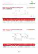
Valvole di blocco e controllo discesa a semplice effetto tipo A con fissaggio a vite
TIPO • TYPE VBCD SE FLV
Single overcentre valves fixing bt screw
VALVOLE DI BLOCCO E CONTROLLO DISCESA A SEMPLICE FFETTO TIPO A CON FISSAGGIO A VITE
CODE
V0392/FLV V0412/FLV
TYPE
VBCD 3/8” SE/A FLV VBCD 1/2“ SE/A FLV
PILOT RATIO
1:4,5 1:4,5
MAX FLOW Lt. / min
40 60
MAX PRESSURE Bar
350 350
3.7
SCHEDA TECNICA/ TECHNICAL DATASHEET
V1 - V2
Valvola utilizzata per controllare il movimento e il blocco dell’attuatore entrambe le direzioni realiz- zando la discesa controllata del carico che non sfugge trascinato dal proprio peso, in quanto la val- vola non consente alcuna cavitazione dell’attuatore. Lo speciale attacco a vite, fornita con la valvola, consente il montaggio della valvola direttamente
E
IMPIEGO:
Guarnizioni: BUNA N standard
Tenuta: trafilamento trascurabile
Taratura standard: 320 Bar
La taratura della valvola deve essere almeno 1,3 volte superiore alla pressione indotta dal carico per consentire alla valvola di chiudersi anche quando sottoposta alla pressione corrispondente al carico massimo.
MONTAGGIO:
Collegare V1 e V2 all’alimentazione, C1 al lato dell’attuatore con flusso libero e flangiare C2 al lato dell’attuatore dove si desidera la tenuta trami-
TIPO / TYPE VBCD SE FLV
SCHEMA IDRAULICO
HYDRAULIC DIAGRAM
ORE
Art.
Rapp. pilot Pilot ratio
Portata max
SCHEDATECNICOAD/ICTECH CODE
Max flow Lt./minV0392/FL
Pressione max
NICAL DASTIGALSAHEET
TYPE GAS
Max pressure V VBCD 3/8” SBE/AaFrLV G 3/8”
V1 - V2
C1
- C2
LV1-VL12 mm mm
C1-C2 100 Gas150
Valvola blocco d
zando la
Lo speci
consente
L2
smfumgge tr L vola non
60
utilizzata
ell’attuat
discesa
L3 L4
mamscinatomm L1 consent
ale attacc
20 22
il monta
per cont ore in un
controlla
o a vite,
ggio dell
dal prmomp L2 e alcuna
L5
78
rollare il
a sola di
ta del ca
fornita c
a valvola
rio pmemso, L3 cavitazio
L6
15
movimen
rezione r
rico che
on la val
direttam
H1
inmqmuant L4 ne dell’a
40
to e il ealiz-
non
H2 H
ommlavamlm- L5 ttuatore.
vola,
30 70
ente
P SW
L6
mm
30 1,
S ESO V
H1
EIGHT
kg US
Th 350 me
ING ALV
H2
E AND
ese valve nts and b
LE ES F
H
PERATI
s are use lock in o
VE
IXIN
N:S
d to cont ne directi
CENTR
Peso
G BY S
Weight
Kg
rol actuator’s mov
on in order to ha
MQ248013
1:4,5
40 V0412/FL
V VBCD 1/2“ SE/A FLV G 1/2” 350
100 150
G 3/8”
60
sull’attua
100
MATERI
20 24
tore.
150
ALI E CA
60
RATTERIS
76
15
20
TICHE:
40
22
30 70
78
30 1,
15
310 a u
40do ca
nder con esn3’t0carr vitations
trol desc y i7t a0wa of the act
ent of a l y,a3s0the uator. Th
oad; load’s weigh valve1p,r3ev5e0nts an e special connecti
MQ248014
1:4,5
60
350
G 1/2”
Corpo: a C1om0p0on e rettific
cciaio zi en1ti5in0ter
ato
ncato ni:6ac0ciai
o t2em0pra
to2te4rmic
am7en6te
15
by 40mo
screw, su
30
unting of
pplied w
70
the valv
ith the v
30
e on the
lve, enables direc
actuator.
1,310
PRESSURE DROPS CURVE
L L1 L2 L3 L4 L5 L6 H1 H2 H S
massimo.
MONTAGGIO:
Collegare V1 e V2 all’alimentazione e flangiare
C1 e C2 direttamente sull’attuatore tramite l’appo-
sita vite.
A RICHIESTA
• pressione di taratura diversa da quella standard
• piombatura (CODICE/P) e predisposizione alla piom- batura (CODICE/PP).
94
OO
CREW
e- ve t
y
on at
Valvole di blocco e controllo discesa a doppio effetto tipo A con fissaggio a vite
Double overcentre valves fixing bt screw
CODICE
CODE
SIGLA
TYPE
RAPP. PILOT PORTATA MAX
PRESSIONE MAX
flow side of the
PILOtTeRAl’TaIOpposita vite.MAX FLOW
A RICHIESTA Lt. / min
• pressione di taratura diversa da quella standard.
V2
ator’s side you want the flow to be blocked by the screw.
• other settings available
• sealing cap (CODE/P) and arranged for sealing cap (CODE/PP)
TASHEET
LO DISCESA A DOPPIO ITE
TIPO / TYPE VBCD DE FLV
SCHEMA IDRAULICO
HYDRAULIC DIAGRAM
BLE OVERCENTRE VALVES FIXING BY SCREW
USE AND OPERATION:
These valves are used to control actuator’s move- mePnEStsO and block in both directions in order to have
N
Valve setting must be at least 1,3 times more than load pressure in order to enable the valve to close even when undergone to maximum load pressure. APPLICATIONS:
Connect V1 and V2 to the pressure flow and flange C1 and C2 directly to the actuator throught the provided screw.
• other settings available
• sealing cap (CODE/P) and arranged for sealing cap (CODE/PP)
Temperatura olio: 50°C - Viscosità olio: 30 cSt
Oil temperature: 50° C - Oil viscosity: 30 cSt
V0422/FLV
V0432/FLV VBCD 1/2“ DE/A FLV 1:4,5 60 350
VBCD 3/8” DE/A FLV
1:4,5 40 350
• piombatura (CODICE/P) e predisposizione alla piom-
batura (CODICE/PP).
PERDITE DI CARICO
MAX PRESSURE Bar
ON REQUEST
MATERIALS AND FEATURES:
Body: zinc-plated steel
Internal parts: hardened and ground steel Seals: BUNA N standard
Tightness: minor leakage
Standard setting: 320 Bar
92 Valve setting must be at least 1,3 times more than load pressure in order to enable the valve to close even when undergone to maximum load pressure.
APPLICATIONS:
Connect V1 and V2 to the pressure flow, C1 to the free
actuator and flange C2 directly to the actu-
3
3.8 Temperatura olio: 5S0C°HECDA- VTEiCscNoICsiAtà/ ToECliHoN: I3C0ALcDSAt Oil temperature: 50° C - Oil viscosity: 30 cSt
TIPO • TYPE VBCD DE FLV
C2 V2
C2
VALVOLE DI BLOCCO E CONTROL
EFFETTO TIPO A CON FISSAGGIO A V VBCD 3/8 - 1/2 SE FLV
FLO
W - Q (l/min)
IMPIEGO:
DOU
Art.
Rapp. pilot Pilot ratio
CODICE
Portata max Max flow
CODE
V0422/FLV VBCD LV0t4./3m2/FiLnV VBCD
SIGLA
C1 - C2
Pressione max Max pressure
TYPE GAS mm
3/8” DE/A FLV G 3/8” 150 1/2“ DE/A FLVBaGr1/2” 150
sull
mm Mm V1-V2
C1-C2
250 11
G
er s G11u0
25
a
0
Co
Co
’attuator
Am TERIAmLIm
rpo: acci
L
mponenti
0 20
ettificato arnizio2n0i
e.
E CARmAmT
aio zinca
L1
interni:
22 : BUN2A4
TERISmTmIC
acciaio te toL2
128 N sta1n2d6a
HE: mm
L3
mprato t
17 rd 19
ermicam
mm
L4
44 50
ente
mm
L5
26 30
mm m
L6
70 3 80 3
WEIGH
a und m doeksgn’ cavitat
H1
by scr
0 2,41
mounti
0 2,70
MATE
T
er control
t carry it
ions of t
H2
ew, suppl
4
0
ng of the
RIALS A
descent
away, a
he actuat
H
ied with
valve o
D FEAT
of a load
s the valv
or. The s
S
the valve
n the actu
URES:
; load’s weight
Peso
e prevents any
pecial connection , enables direct
Weight ator. Kg
MQ248015
1:4,5
40
350
Ten
G 3/8”Tar La
uta: trafil
150
atura sta
taratura
amento t
250
ndard: 3
della val
rascurab
110
20 Bar
vola deve
ile
20
essere a
22
lmeno 1,
3128
17
Body: 4In4tern Seals:
zinc-plat al p2a6rts:
BUNA N
ed steel har7de0ned standar
an3d0gro d
und2ste,e4l14
MQ248016
1:4,5
60
350
vol G 1/2”co
sott
te superi ns1en5tir0e a oposta a
ore alla p lla2v5a0lvol lla pressi
ressione a1d1ic0hiu one corr
indotta d de2rsi0anc isponden
al carico he2q4uan te al cari
per do126 co
19
Tightn
50
Stand
ess: mino
30
ard settin
r leakag
80
g: 320 B
e 30 ar
2,700
76 PERDITE DI CARICO PRESSURE DROPS CURVE
C2 V2 C1 V1
V2 C2 V1 C1
ON REQUEST
Δ P (BAR)
