
Page 75 - Hydraulics Cylinder
P. 75
UK Hydraulic components • DE Hidraulik Komponenten • FR Composants hydrauliques • ES Componentes hidráulicos
V0424 VBCD 3/8” DE/FL 1:4,5 40 Valvole di blocco e controllo discesa a doppio effetto a flangia
350 350
Double overcentre valves flangeable
V0434
VBCD 1/2“ DE/FL 1:4,5
60
TASHEET
CODICE
CODE
V0424 V0434
SIGLA
TYPE
VBCD 3/8” DE/FL VBCD 1/2” DE/FL
Valvola utilizzata per controllare il movimento e
BASETTA PER VALVOLA /
VALVE’S FLANGE:
tore. Gli attacchi a flangia consentono il montaggio diretto della valvola sull’attuatore.
MATERIALI E CARATTERISTICHE:
Corpo: acciaio zincato
Componenti interni: acciaio temprato termicamente e rettificato
Guarnizioni: BUNA N standard
MATERIALS AND FEATURES:
Body: zinc-plated steel
Internal parts: hardened and ground steel
g
1
Oil temperature: 50° C - Oil viscosity: 30 cSt
CODICE SIGLA RAPP. PILOT PORTATA MAX
CODE TYPE PILOT RATIO MAX FLOW Lt. / min
PRESSIONE MAX
MAX PRESSURE Bar
3
VALVOLE EFFETTO
DI BLOCCO E CONTRO A FLANGIA
V1 - V2
C1 - C2 L L1 L2 H
S
75
IMPIEGO:
LLO DISCESA A DOPPIO
TIPO / TYPE VBCD DE FL
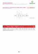
SCHEMA IDRAULICO
HYDRAULIC DIAGRAM
PESO DOUBLE OVERCENTRE
WEIGHT VALVES FLANGEABLE
GAS mm mm mm mm mm mm kg
G 3/8” G 1/2”
il blocco dell’attuatore in entrambe le direzioni realizzando la discesa controllata del carico che noØn9sfugge tr1a5s0cinato24d8al prop1r1io0 peso, 6in0 quanto3l0a valvola non consente alcuna cavitazione dell’attua-
USE AND OPERATION:
2,012 These valves are used to control actuator’s move- ments and block in both directions in order to have
Ø9 150 248 110
60 30
1,980 a under control descent of a load; load’s weight doesn’t carry it away, as the valve prevents any cav- itations of the actuator. Flange ports enable direct mounting of the valve on the actuator.
Art.
Rapp. pilot Pilot ratio
CODICE/ Portata maBx85
Max flow Lt./min
CODE
00Pressione max Max pressure
Bar
Tenuta: trafilam
Taratura standa
V1-V2
La taratura dell
volte superiore coGnsaenstire alla sottoposta alla
ento trascura rd: 320 Bar
a valvola dev aClla1pr-eCssio2ne valvola di chi pressione corr
ile
e essere alme indotLta dal c udersi anche q ispondente al
no 1,3 aricoLp1er
uando carico
Se Ti
Va L2 St
lo ev
als: BUNA N
htness: minor
andard setting
H
lve setting mu
90
ad pressure in en when unde
standard
leakage
: 320 Bar
S
st be at least
order to ena rgone to max
Peso
Weight
1,3 times more than
ble the valve to close imum loKadgpressure.
MQ249014
1:4,5
40
350
massimo.
MONTAGGIO:
G 3/8”
Collegare V1 e
Ø9
V2 all’alimen
150
tazione e flan
giare
248
AP
110 Co C
PLICATIONS: nnect V1 and
60
and C2 dire
30
V2 to the pre
ctly to the act
2,012
ssure flow and flang
uator.
MQ249013
1:4,5
60
350
C1 e C2 diretta
GAR1IC/H2IE”STA
mente sull’att
Ø9
uatore.
150
248
110 O •
N REQ6U0EST other settings
30
available
1,980
Flangiabile • Face mounting • Plattenanschluss Materiale • Material: Acciaio • Steel • Stahl
• pressione di taratura diversa da quella standard.
• piombatura (CODICE/P) e predisposizione alla piom- batura (CODICE/PP).
PERDITE DI CARICO
• sealing cap (CODE/P) and arranged for sealing cap (CODE/PP)
Temperatura olio: 50°C - Viscosità olio: 30 cSt
PRESSURE DROPS CURVE
b
e
VBCD 3/8 - 1/2 DE FL FLOW - Q (l/min)
C2 V2 C1 V1
TIPO • TYPE VBCD DE FL
SCHEDA TECNICA/ TECHNICAL DA
3.6
V2 C2 V1 C1
Δ P (BAR)
