
Page 33 - Hydraulics Cylinder
P. 33
COMPONENTI OLEODINAMICI
COMPONENTI OLEODINAMICI
OLEODYNAMIC COMPONENTS - COMPOSANTS OLEODINAMIQUES - ÖLDYNAMISCHE BESTANDTEILE - COMPONENTES OLEODINÁMICOS
UK Hydraulic components • DE Hidraulik Komponenten • FR Composants hydrauliques • ES Componentes hidráulicos
OLEODYNAMIC COMPONENTS - COMPOSANTS OLEODINAMIQUES - ÖLDYNAMISCHE BESTANDTEILE - COMPONENTES OLEODINÁMICOS
ELETTROVALVOLE CETOP 2
Elettrovalvole cetop 2
ELELCETTRTICROVAVLAVLEVSOCLEETOCPET2OP 2
ECleOcNtrTicRvOaLlvEesDcIRetEoCpT2IO•NCoCnEtrToOlePd2irection cetop 2 • Electroventilen cetop 2 • Electrovälvula cetop 2 ELECTRIC VALVES CETOP 2
ELECTROVENTILEN CETOP 2 CONTROLE DIRECTION CETOP 2
ELECTROVENTILEN CETOP 2
ELECTROVÄLVULA CETOP 2 COMPONENTI OLEODINAMICI
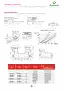
Caratteristiche tecniche Technical characteristics
ELECTROVÄLVULA CETOP 2
OLEODYNAMIC COMPONENTS - COMPOSANTS OLEODINAMIQUES - ÖLDYNAMISCHE BESTANDTEILE - COMPONENTES OLEODINÁMICOS
Grandezza: ISO 228 CETOP RP 121 Size: ISO 228 CETOP RP 121 H-4-2-4-PO2 CETOP2 H-4-2-4-PO2 CETOP2
Caratteristiche tecniche Technical characteristics
Portata massima: 20 l/min. Max flow: 20 l/min.
Grandezza: ISO 228 CETOP RP 121 Size: ISO 228 CETOP RP 121 Caratteristiche tecniche Technical characteristics
Pressione massima d’esercizioEsLuEATT-BR-OPV:A3L0V0ObLaErCETOP 2 Min operation pressure on A-B-P: 300 bar
H-4-2-4-PO2 CETOP2 H-4-2-4-PO2 CETOP2 Pressione massima in T: Max pressure in T:
Grandezza: ISO 228 CETOP RP 121 Size: ISO 228 CETOP RP 121
Portata massima: 20 l/min. ELECTRIC VALVES CETOP 2 Max flow: 20 l/min.
dinamica = 180 bar - statica = 210 bar dynamic = 180 bar - static = 210 bar
H-4-2-4-PO2 CETOP2 CONTROLE DIRECTION CETOP 2 H-4-2-4-PO2 CETOP2
Pressione massima d’esercizio su A-B-P: 300 bar Portata massima: 20 l/min. ELECTROVENTILEN CETOP 2
Min operation pressure on A-B-P: 300 bar Max flow: 20 l/min.
Pressione massima in T: ELECTROVÄLVULA CETOP 2 Pressione massima d’esercizio su A-B-P: 300 bar
Max pressure in T:
Min operation pressure on A-B-P: 300 bar
dinamica = 180 bar - statica = 210 bar Pressione massima in T:
dynamic = 180 bar - static = 210 bar Max pressure in T:
dinamica = 180 bar - statica = 210 bar
dynamic = 180 bar - static = 210 bar
Caratteristiche tecniche
Technical characteristics
Grandezza: ISO 228 CETOP RP 121
H-4-2-4-PO2 CETOP2
Size: ISO 228 CETOP RP 121 H-4-2-4-PO2 CETOP2
Max flow: 20 l/min.
Min operation pressure on A-B-P: 300 bar MaxpressureinT:
dynamic = 180 bar - static = 210 bar
Portata massima: 20 l/min.
dinamica = 180 bar - statica = 210 bar
Quantità superficie
Pressione massima d’esercizio su A-B-P: 300 bar
PressionemassimainT: diattacco Quantità superficie
Mounting plane quality
di attacco
Mounting plane quality
Quantità superficie di attacco Mounting plane quality
Art. ART. 12VDC
12VDC ART. 12VDC
ART.
1
Art.
24VDC
24VDC
ART.
24VDC
ART. ART. 2VDC Sigla 24VD
Sigla
Code
Sigla
Code
Code
MK158
Sigla C Code
Simbolo
Circuit
Simbolo
A2
Simbolo
Circuit
Circuit
Simbolo
Circuit
Direzione del flusso durante
il passaggio al centro
Direzione del flusso durante
Direzione del flusso durante
Oil direction during shift
il passaggio al centro
Dirielzpioansesdaegl gfluiossaoldcuerannttreo Oil direction during shift
il passaggio al centro
Oil direction during shift
Oil direction during shift
MK158013
MK MK
MK158113 MK
158013
158010 MK158 158011 A2 MK158
113 110 111 116 112 114 115
B2 C2 D2 E2 C11A A11C
34
MK15M80KM1K351850810
MK
13 MKM1KM518K5181513811013
1 5 8 0 1 6 B A2 A2 2 M K 1 5 8
MK15M80KM10K518508101
MK
10 MKM1KM518K518151081110 MK
158012 CB2B22 MK158 158014 MK158
MK15M80KM11K518508106
11 MKM1KM518K5181511811611MK
158015 DC2C22MK158
MK15M80KM16K518508102
16 MKM1KM518K5181516811216
ED2D22
MK15M80KM12K518508104
12 MKM1KM518K5181512811412
C1E1E2A2
MK15M80KM14K518508105
14 MKM1KM518K5181514811514
AC1C1C11AA
MK1580M15K1580
15 MK1M58K11558115
AA111CC
34
3334
