
Page 106 - Hydraulics Cylinder
P. 106
UK Hydraulic components • DE Hidraulik Komponenten • FR Composants hydrauliques • ES Componentes hidráulicos
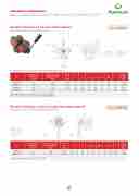
Deviatori di flusso a 6 vie (con centro aperto)
TIPO•TYPEDF6
CODICE
CODE
V0920
V0940
SIGLA
TYPE
DF 6 VIE 3/8” DF 6 VIE 1/2”
PORTATA MAX
MAX FLOW Lt. / min
35 60 100 180
PRESSIONE MAX
MAX PRESSURE Bar
250 250 250 250
16.4
SCHEDA TECNICA/ TECHNICAL DATASHEET
6-ways diverter valves (with opened centre)
DEVIATORI DI FLUSSO A 6 VIE
V0950 DF 6 VIE 3/4”
V0960
DF 6 VIE 1”
SCHEMA IDRAULICO (con centro aperto) HYDRAULIC DIAGRAM (with opened centre)
TIPO / TYPE
DF 6 A RICHIESTA (con centro chiuso) ON REQUEST (with closed centre)
6-WAYS DIVERTER VALVES
16
SCHEDA TECNICA/ TECHNICAL DATASHEET
IMPIEGO:
Valvole formate da due deviatori a 3 vie accoppiati: ognuna delle due sezioni ha la funzione di deviare il
A richiesta con centro chiuso • On request with closed centre
V0932 DF 6 VIE 1/2” ACCIAIO 60 300 • Centro chiuso (CODICE/CC)
USE AND OPERATION:
This valve is made up by two 3-ways diverters coupled: PESO each of the 2 parts is used to divert the inlet flow towards
m
O
Aw
Art.
Portata max Max flow Lt./min
CODICE SIGLA
Pressione max
CODE TYPE
V0920 DF 6 VIE 3/8” Max pressure
V0940 DF 6 VIE 1/2”
Bar
V0950 DF 6 VIE 3/4”
A-B
P-T L flusso da u
A-B
GAS mm
un’unica le
sezioni. Po
P-atTtuatori. G 1/2” 87 GAMSATERIAL
G 3/8” 76
G 3/4” 103
Corpo: ghi
na sola alime
L1 L2
mm mm
va si azionan ssono essere 140 68
L
145 80
I E CARATTER
sa 150 94
ntazione a du
L3 L
mm m
o contempora utilizzati per a 45
L1
ISTICHE:
51 3
55
e uscite. Tram
4 ØG
m mm
neamente le zionare due
26 8,5
2 8,5 32 11
L2
ite
WEIGHT Kg.
H
mm
due
117 125 140
L3
1,688
2,628 4,634
two ports. same time.
L4
MATERIAL
The single leve It’s ideal to c
ØG
S AND FEATU
r controls bot ontrol 2 actuat
H
RES:
h the parts at the ors. Peso
Weight Kg
MR289010
35
V0960 DF 6 VIE 1” 250
GC1o”mpo1n0e5n G 3/8”
rettificato
ti inte15r2ni: acc9i8 76
aio tem60prato 140
3t2ermic1a1mente 68
e155 4,238 45
Body: cast i Internal pa
26
Seals: BUN
ron
rts: hardened
8,5
A N standard
117
and ground st
eel 1,688
MR289011
60
250
G 1/2”
Guarnizio
Tenuta: tra
87
ni: BUNA N st
filamento tras
andard
145
curabile
80
51
32
Tightness:
8,5
inor leakage
125
2,628
MR289012
100
250
G 3/4”
MONTAG
GIO:
103
150
94
55
32
APPLICATI
NS:11
140
4,634
MR289013
180
250
Collegare Ge1B”alprim
P e P’ alle du o at1tu0at5ore e
e alimentazion le b1oc5ch2e A’
i, le bocche eB’a9l8second
o 60
Connect P a B t3o 2the first
nd P’ to the 2 actu1at1or and
pressure flo por1ts5A5’and
s, ports A and B’to4the,2se3co8nd
Montaggio in linea • Line mounting • Reihenmon
a
288
Materiale • Material: Ghisa • Cast iron • Hydraulikguss
V0930
SCHEDA TECNICA/ TECHNICAL DATASHEET
CO
SIGLA
TYPE
DF 6 VIE 3/8” ACCIAIO 40 300
t
ge
A’, con leva in pos. 2 P alimenta B e P’ alimenta B’.
P’ to A’; with lever in position 2, P is connected to B and P’ to B’. With lever in central position all ports are connected among each other (opened centre).
D
CODE
ICE
MAX FLOW MAX PRESSURE
Con leva inLtp. /omsinizione centrale leBarbocche di ogni sezio- ne sono tra loro collegate (centro aperto).
attuatore. Con leva in pos. 1 P alimenta A e P’ alimenta
actuator. With lever in position 1, P is connected to A and
PORTATA MAX PRESSIONE MAX
16.5
O A 6 VIE IN ACCIAIO
A RICHIESTA:
A RICHIESTA:
• Closed centre (CODE/CC)
Deviatori di flusso a 6 vie in acciaio (con centro aperto)
TIPO • TYPE DF 6A
6-ways diverter valves, steel body (with opened centre)
TIPO / TYPE DF 6A
SCHEMA IDRAULICO
HYDRAULIC DIAGRAM
P A/A’
P
B/B’
16
AYS DIVERTER VES, SATrEt.EL BO
Portata max DY Maxflow
Lt./min
Pressione max
Max pressure A-B CODICE SIGLA P-T CODE TYPE GAS
Bar
A-B
P-T
GAS
L L1
mm mm
L2
mm
L
L3
mm
L1
L4
mm
L2
ØD H
mm mm
L3
H1 G
mm mm
L4PESO WEIGHT
Kg.
ØD
H
H1
G
Peso Weight Kg
ND OPERATION:
lveisuMsedRto2d9iv0er0tt1he0flowfr
om 2 ways in tow4a0rds
V0930 DF 6 VIE 3/8” ACCIAIO G 3 300
G 3/8”
/8” 60 140
60
58 32
140
25
47 5874
32
96
25
8 1,540
47
74
96
M8
1,540
(two at time alternatively).The tors. MR290011
y are used to control
60
V0932 DF 6 VIE 1/2” ACCIAIO G 1/ 300
2” 69 145
G 1/2”
66 3
69
7 27
145
47 6683
105 M
37
8 2,294
27
47
83
105
M8
2,294
IMALSaAteNDriFaElAeTU•RESM: aterial: Acciaio • Steel • Stahl zinc-plated steel
l parts: hardened and ground steel
6-W VAL
USE A
a This va 4 ports 2 actua
MATER
Body:
Interna
Seals: BUNA N standard Tightness: minor leakage
M
APPLICATIONS:
Connect P and P’ to the 2 pressure flows, ports A and A’ to the first actuator and ports B and B’ to the second actuator. With lever in position 1, P is connected to A and A’; with
l lever in position 2, P is connected to B and B’. Use with lever in central position is not recommended.
290
106
S
e
